DMV DISPLAY
- In this project I had to design a DMV Display by creating a digital circuit that displays the counting from 00 to 80.When the display reaches 80 it restarts at 00, just like the ones used in a DMV office. After that we had to add in a reset switch, that will reset the count to 00, and begin all over again after it is toggled again. The whole counter itself is controlled by a clock that is connected through multiple flip-flops in order to be able to the number readings that we were supposed to get. After we had built this in Design mode on MultiSim, i had to re-build it in PLD mode, and then upload it to a chip to be able to test it on a photoboard
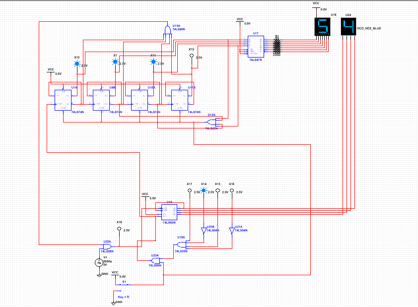
muLTISIM CIRCUIT
| dmv_display_design_mode.ms14 |
PLD CIRCUIT
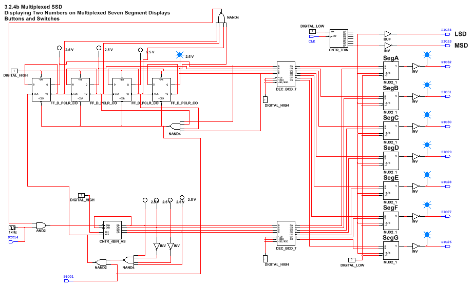
.When in MultiSim, there are two different types of ways you can build a circuit, you can either build it in Design mode, and then build it on a regular breadboard with integrated circuits, or you can try PLD mode (Programmable Logic Design). In PLD mode, you can add pin assignments. When you have the Diligent Cmod S6 chip like we use in our class, you can assign the inputs, outputs, and connectors to different circuit to a pin, and then you have to wire that pin to the desired place on the breadboard or photoboard. The benefits of this system, is that since most of it is done on multisim, there is less room for error, compared to constructing the whole system from scratch on a breadboard. There is also less wires used, making it even easier to troubleshoot any issues if you were to have some, because even though it is all done on the computer, there is still room for error. Basically, the design mode maps out what you need to construct on your breeadboard like a blueprint would, whereas PLD mode does that for you, and all you have to do is upload it to this chip, and wire your input and output pins to the chip, in a much easier process
BILL OF MATERIALS
- 15 wires
- CMOD S6
- CMOD S6
CONCLUSION QUESTIONS
Upon completion of this project, i have learned many things, and my understanding of how asynchronous counters work has been greatly increased. One thing i learned in this project, was how to distinguish an SSI and MSI circuit. SSI is the acronym for Small Scale Integration, and MSI is Medium Scale Integration. AN example of a SSI gate is a 74LS74, the basic D Flip-Flop, as this is only 1 flip=flop, this is considered to be Small Scale Integration. AN example of Medium Scale Integration would be the 74LS93 gate, as this one contains a whopping 4 flip-flops internally, compared to the single flip-flop in the 74LS74, so this is considered the Medium Scale Integration. The MSI gates are a lot more useful when trying to save space, but have when downside, an MSI gate cannot be altered to start at a numerical value other than 0, and will therefore only start at the number 0. When using any asynchronous counter, one must realize that the term asynchronous means "not in sync", and in this case, the counter is not in sync with the clock. So in some situations dealing with asynchronous counters, you may face delays between certain parts and the clock, causing a ripple in the graph readings. This is known as the ripple effect, and will most likely occur in every asynchronous counter that is powered by a clock. The way i created was project was very fluent and logic. My ones display was made up of a MSI asynchronous counter (74LS93) and was hooked up to a HEX display, using inverters and NAND gates to detect a 10 on the scale, but reset to 0 once you see the number 9. My tens digit display was also constructed with asynchronous counters, but was a SSI circuit build. There were 4 flip-flops, wired together to be able to detect a 9, but only show you an 8, as required in the design constraints. After these two separate counters were built, i wired them together to be able to function as i would like them to, so it would count normally as anything else would. So now the whole circuit would count to 80, and then stop. But there was one final thing that had to be taken care of, the reset switch. I constructed this with a regular SPDT switch, and wired it to both the tens and ones circuits, specifically to the wires where the clears on the flip flops were located, because that is what resets it to 0, as shown in the above picture. Now my project was complete! The circuit counted from 00 to 80 and then stopped, giving me time to pause at any number in between. After it stopped at 80, i could simply toggle the switch to reset to 00, and then toggle it again to have it count up to 80 again
