60 second timer
I had to design a timer that counted from 00 to 59. I believe the similarities between these project is that they both operated from the same external clock, mine was powered to 100Hz, and i believe that they were both also medium scale integration. The only differences was the new LS163 gate, JK flip-flops, and the DMV display had to count to 80 and stop, whereas this circuit had to reset once it hit 59
Explanation
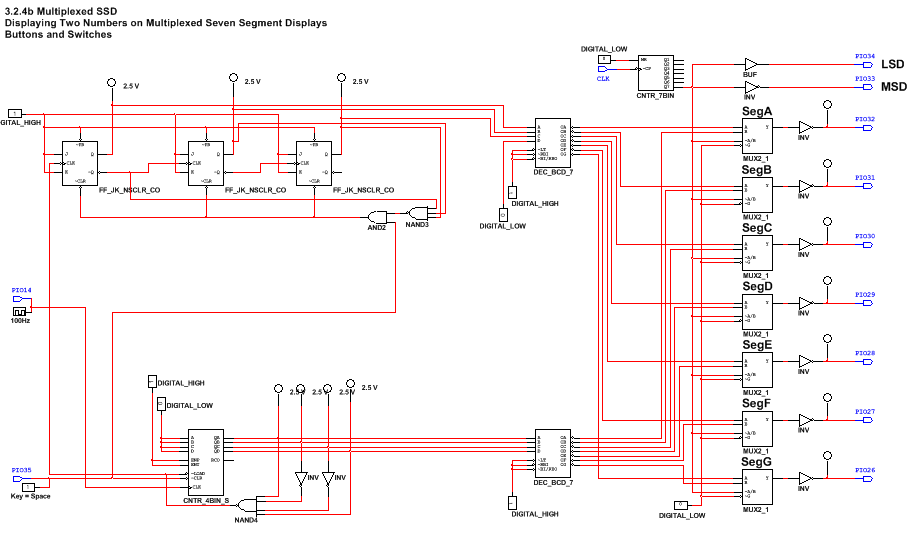
We were given the task of constructing a sixty second timer that counts from 0 to 59, and then resets back to 0 and continues counting up. We were also prompted to add in a reset switch that resets the whole circuit to 0 at any time during the simulation. After this was built in PLD mode we had to upload it to the CMOD chip to be able to test it, after we made sure it was working on the board.
conclusion
In the end, i have extended my knowledge of this subject to an immeasurable extent, far greater than what i have had before. One thing i learned in this project, was how to distinguish an SSI and MSI circuit. SSI is the acronym for Small Scale Integration, and MSI is Medium Scale Integration. AN example of a SSI gate is a 74LS74, the basic D Flip-Flop, as this is only 1 flip=flop, this is considered to be Small Scale Integration. AN example of Medium Scale Integration would be the 74LS93 gate, as this one contains a whopping 4 flip-flops internally, compared to the single flip-flop in the 74LS74, so this is considered the Medium Scale Integration. The MSI gates are a lot more useful when trying to save space, but have when downside, an MSI gate cannot be altered to start at a numerical value other than 0, and will therefore only start at the number 0. When using any asynchronous counter, one must realize that the term asynchronous means "not in sync", and in this case, the counter is not in sync with the clock. So in some situations dealing with asynchronous counters, you may face delays between certain parts and the clock, causing a ripple in the graph readings. This is known as the ripple effect, and will most likely occur in every asynchronous counter that is powered by a clock. Also, the 74LS163 can only be an up counter, but you can program any start and it stops with the number detected. Logic gate 74LS193 can be an up or down counter and is able to start with any number, but you have to detect the next number to stop at the number you wanted it to. For this project i created two different display counters, and connected them together to count in sync. I made this project a lot easier by just loading up my DMV display in PLD mode, and re doing the whole left side, and replacing most of the parts. Using a 74LS163 counter and some inverters, i made it possible for the bottom part to be able to count from 0-9, just as we were supposed to. Then after that, i used 3 JK flip-flops at the top to make it count to 5, but detect a 6 and reset. After wiring these together and manipulating a few parts, the circuit was able to count from 00 to 59, and the reset and start all over again. The final thing to do now before uploading to the board was to add in a reset switch, so i could reset the whole simulation to zero whenever i felt the need to, so i built it in. After the successful completion of this project, i went around and helped my classmates with their projects, and the only major difference i could find between circuits is confusion with understanding how the LS163 works, since it is a "what you see is what you get circuit", but i was able to help in most circumstances.
